
High-performance hammer crushers depend on rotor design more than any other rotating part. This Rotor design guide shows how to match mass and speed to feed, lock hammers so force stays in the rock, and build the assembly so it does not break or go out of balance. Follow it and the Rotor delivers stronger crushing and more uniform particle size.
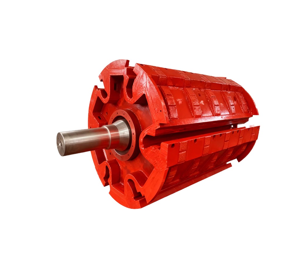
Start With Duty Before You Size the Rotor
Feed numbers that set Rotor mass and tip speed
Before a Rotor drawing is opened, write down feed hardness, moisture, and tramp frequency. A high-performance Rotor needs enough mass so hammers break hard ore instead of stalling. Diameter and hammer count follow those numbers. Optimized structural design on that Rotor then gives stronger crushing force and more uniform particle size. Copying a worn Rotor often copies the old limit.
Empty hits that fatigue the Rotor even when rock is gone
A rotor in a high-performance hammer crusher takes loaded hits and empty blows when the feeder gaps. Those cycles work fillets and pin bores. We radius transitions so the Rotor core can flex without cracking. Springs of spring steel, high-strength steel wire, or carbon steel will not save a whipping Rotor. Design for the empty-hit case the plant really runs.
Chamber width so the Rotor does not leave a coarse tail
Rotor width and hammer reach must match the chamber so rock cannot sneak past the tips. A short Rotor leaves a coarse tail and extra circulating load. Optimized structural design keeps crushing force on the feed and particle size more uniform. We match liner profile to Rotor diameter. Similar chambers let one Rotor family serve more than one unit.
Lock Hammers to the Rotor So Force Stays in the Rock
Bimetallic heads that keep the Rotor from losing a hammer
Customizable bimetallic composite hammer heads put a hard, wear-resistant face on a strong handle so a broken hammer does not wreck Rotor balance. The head wears; the handle bends and solves easy breakage. A high-performance Rotor stays at speed when hammers stay intact. We cut Rotor seats and pins for that handle, not for a single-alloy hammer that snaps.
Seat and pin fits that stop the Rotor from shaking
If Rotor seats ovalize or pins slop, hammers rock and impact turns into heat. Optimized structure machines the seats so crushing force stays on the Rotor axis and particle size stays even. Loose fits make a high-performance Rotor loud and the product coarse. We hold those bores to the drawing so the Rotor hits as the operator set the gap.
Balance the dressed Rotor, not a bare disc pack
A high-performance Rotor should be balanced with hammers, pins, and wear plates already on it. Balancing a bare Rotor does not represent the running machine. Leftover unbalance pounds the bearings and loosens seats. We assemble the Rotor as it will hang, then add or remove mass. Skipping that step is how plants later say the Rotor never ran smooth.
Build the Rotor in the Shop the Way It Will Run in the Mine
Forge the alloy steel shaft inside the Rotor
The main shaft that carries a high-performance Rotor should be forged from alloy steel, not cast. Forging lines the grain with bending and torsion so the Rotor survives mining duty. Journals are machined after forge and heat treat. We do not put a cast shaft in a Rotor. This is a heavy engineering part for crushers, not electronics.
Change Rotor length and discs for different hammer crushers
A custom rotor can be made for various hammer crushers and mining equipment when duty is close. We alter length, discs, and hammer pairing to each housing. Hammer heads stay on hammer crushers. Blow bars are impact-crusher parts and a separate family; not a Rotor option. Fit, bolts, and clearance still decide if that Rotor is suitable.
Freeze the Rotor print before anyone talks about a date
Custom Rotor work waits for a frozen print. A clear sample of an existing Rotor moves sooner. When seats or length keep changing, the calendar stretches—normal when drawings take time. We will not give a firm date on a moving Rotor drawing. After it freezes, forge, machine, balance, and inspect run in order so the Rotor hangs ready.
Conclusion
A high-performance Rotor for a hammer crusher is sized from duty, locked so hammers do not waste energy, and built with a forged alloy steel shaft and a frozen print. Do those things and crushing force and particle size stay where the plant set them. Judge the rotor after it has seen real feed, not when the crate lands.
FAQ
Q: What do I define first in this Rotor design guide?
A: Hardness, moisture, tramp, and chamber. They set Rotor mass, diameter, width, and hammer count before steel is cut.
Q: Why put bimetallic composite heads on the Rotor?
A: Hard wear-resistant head and strong handle. Breakage drops, so the Rotor keeps its balance and crushing force.
Q: Can the Rotor shaft be a casting?
A: No. Forge it from alloy steel. A cast shaft is a fatigue risk under bending and torsion.
Q: Will one Rotor fit all my hammer crushers?
A: Only if duty and chamber match. Otherwise change length and seats. Blow bars are not a Rotor substitute.
Q: Why won’t you give a firm date on day one?
A: Custom Rotor jobs follow the frozen print. Drawing changes stretch the calendar. We date a settled Rotor, not a moving one.
Ready for Your Next High-Performance Rotor? Talk to Huan-Tai
If seats are oval, hammers are snapping, or the Rotor will not stay in balance, send the drawing or a marked sample. Xian Huan-Tai Technology and Development Co., Ltd. has 30 years making custom non-standard mechanical parts for mining and equipment companies. You get a technical team that works to your performance numbers, a production team that owns quality from steel to final inspect, and service that answers. Email inquiry@huan-tai.org with duty and what failed. We will come back with the next step.
References
- Prasher, C.L. Crushing and Grinding Process Handbook. John Wiley & Sons, 1987.
- Lowrison, G.C. Crushing and Grinding. Butterworths, 1974.
- Gupta, Ashok, and Denis Yan. Mineral Processing Design and Operations. 2nd ed. Elsevier, 2016.
- Fuerstenau, Maurice C., and Kenneth N. Han. Principles of Mineral Processing. Society for Mining, Metallurgy, and Exploration, 2003.
- King, R.P. Modeling and Simulation of Mineral Processing Systems. 2nd ed. SME, 2012.
