
The main shaft is the main part of a crusher’s structure. It’s the moving or set column in the middle that does all the breaking. The main shaft of a cone or gyratory crusher moves the mantle and makes the concave and eccentric motions that crush the rock. Any change in the shape of the shaft directly impacts the performance of the crusher, the life of the bearings, and the uniformity of the flow. This means that the design has to find a balance between rotational strength, twisting resistance, and measurement accuracy.
Key Design Principles of a Crusher Main Shaft
Geometry and Load Path
The main shaft of a crusher is designed based on the loads it must carry while in use. The shaft of a cone crusher holds both the weight of the breaking head assembly and the forces that are created when the cone rocks back and forth. This means that the shaft needs to be the right size for both the standing load and the twisting and torque forces that build up over millions of rounds of use. The shoulder shape, curve profile, and thickness of the shaft are all determined to keep stress levels safe over the life of the equipment.
Material Selection for High-Load Conditions
Main shafts for crushers used in mining are usually made of alloy steel, which is formed or cast and has high tensile strength, hardness, and wear resistance. When the crusher works with hard or rough rock, the material needs to be able to withstand pressure loads without getting surface cracks that could spread and cause the structure to fail. After the material is formed, it is heated to improve its properties even more. This creates a hardness gradient that covers the bearing contact areas while keeping the shaft body strong enough to take pressure without breaking.
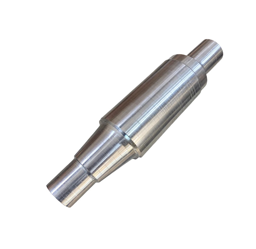
Dimensional Precision and Surface Finish
On a crusher’s main shaft, the bearing seats, taper surfaces, and thread features all need to be made to very close specs for size. Bearing seats need very tight circle control and a very smooth surface finish. A rough or out-of-tolerance seat makes the load on the bearings uneven and speeds up wear. Before finish machining, resin sand or lost foam casting methods are used to get an exact near-net-shape geometry. This cuts down on material removal and makes sure the base casting doesn’t have any holes or other features that could damage the surface during milling.
How the Main Shaft Interacts With Other Crusher Components
Relationship With the Eccentric Assembly
In a cone crusher, the main shaft sits within or passes through the eccentric assembly, which rotates around it to create the gyratory motion that crushes material. The shaft’s surface finish and dimensional accuracy at the eccentric interface directly affect how smoothly this motion is transmitted and how evenly wear develops over time. A Main Shaft that is correctly sized and finished supports the eccentric assembly in maintaining consistent nip angle and closed-side setting throughout the crusher’s operating life.
Bearing Support and Alignment
The main shaft is supported at its upper and lower ends by heavy-duty bearings housed within the crusher frame. The position and geometry of these bearing seats on the shaft determine how well the shaft stays aligned under eccentric loading. Misalignment at the bearing seats causes uneven load distribution across the bearing rollers, reducing bearing life significantly. This is why dimensional inspection at every shaft bearing journal is a mandatory step in quality-controlled Main Shaft production, not an optional verification.
Interaction With the Mantle and Crushing Chamber
At its upper end, the crusher main shaft carries the mantle — the wear surface that contacts rock during crushing. The taper fit between the shaft and the mantle hub must be precise enough to prevent relative movement during operation, which would cause fretting and eventual loosening under load. The taper geometry is critical: too shallow and the mantle may work loose; too steep and removal for wear replacement becomes difficult. Getting this interface right requires both careful design and accurate machining of the shaft taper.
Sourcing and Manufacturing Custom Main Shafts
Custom Drawing Support and Design Confirmation
Many crusher main shafts in long-term service are non-standard — either because the original OEM no longer supports the machine, or because the equipment has been modified over its service life. In these cases, custom manufacturing from customer-supplied drawings or reverse-engineered samples is the most practical solution. Supporting custom drawing design from the inquiry stage through to production sign-off ensures that the final shaft meets the dimensional and material requirements of the specific crusher it will be installed in.
Manufacturing Process and Quality Inspection
The main shaft is produced using a forging process, which provides superior mechanical strength, internal integrity, and fatigue resistance required for crusher applications. After forging, rigorous dimensional inspection is carried out to verify that all critical features are within tolerance before machining begins, preventing costly issues from being identified late in the production process. Post-machining inspection of all bearing journals, taper features, and thread forms completes the quality verification before the shaft is approved for shipment.
Lead Time for Custom Main Shafts
Standard main shaft profiles can be produced within a manageable and predictable timeframe. Custom shafts — particularly those requiring new casting patterns, unusual material specifications, or multiple rounds of drawing confirmation — naturally take longer. The production process involves casting, heat treatment, multi-stage machining, and inspection, each of which must be completed correctly in sequence. Providing complete drawings and clear material requirements at the inquiry stage is the single most effective way to keep the process moving without unnecessary delays.
Conclusion
The crusher main shaft is a precision-engineered component that sits at the heart of every cone and gyratory crusher’s performance. Its design, material, and dimensional accuracy all determine how reliably the crusher operates and how long it lasts between major maintenance events. For mining equipment operators and procurement teams, sourcing a shaft from a manufacturer with genuine casting and machining capability is the foundation of a reliable crusher rebuild or new machine build.
FAQ
Q1: What material is used for crusher Main Shafts?
Alloy steel is the standard material for mining-grade crusher main shafts, providing the tensile strength, toughness, and fatigue resistance required for continuous high-load operation.
Q2: Can a Main Shaft be manufactured from a drawing or sample?
Yes. Custom main shafts can be produced from customer-supplied engineering drawings or reverse-engineered from a physical sample, covering all critical geometry including bearing seats, tapers, and thread features.
Q3: What casting process is used for Main Shaft production?
Resin sand and lost foam casting are both commonly used, selected based on shaft geometry, size, and required dimensional accuracy. Both methods are followed by rigorous dimensional inspection.
Q4: How do I know if my crusher’s Main Shaft needs replacing?
Visible surface damage at bearing seats, measurable wear beyond tolerance, bending deformation, or cracks at stress concentration points are all reliable indicators that shaft replacement should be planned.
Q5: What affects the lead time for a custom Main Shaft?
Casting pattern availability, material procurement, drawing confirmation rounds, and the complexity of the shaft geometry all influence how long production takes. Providing complete drawings upfront shortens the process considerably.
Build Your Next Crusher Main Shaft With a Partner Who Knows the Details
At Xian Huan-Tai Technology and Development Co., Ltd., we’ve spent over 30 years producing precision castings and machined parts for mining and engineering equipment customers worldwide. Our production team manages quality from casting through final inspection, and our technical team works directly with customers to confirm drawings and specifications before production begins. Whether you need a standard replacement or a fully custom Main Shaft, we’re ready to deliver. Send your inquiry to inquiry@huan-tai.org — let’s get your project moving.
References
- Wills, B. A., & Finch, J. A. (2015). Wills’ Mineral Processing Technology: An Introduction to the Practical Aspects of Ore Treatment and Mineral Recovery (8th ed.). Butterworth-Heinemann. Section on crusher design principles and main shaft loading in cone and gyratory crushers.
- Metso Corporation. (2012). Crushing and Screening Handbook (5th ed.). Metso Minerals. Coverage of main shaft geometry, eccentric assembly interaction, and wear management in cone crushers.
- Shigley, J. E., & Mischke, C. R. (2001). Mechanical Engineering Design (6th ed.). McGraw-Hill. Chapters on shaft design for fatigue loading, material selection, and bearing seat tolerance requirements.
- Gupta, A., & Yan, D. S. (2006). Mineral Processing Design and Operations: An Introduction. Elsevier. Analysis of crusher component design including main shaft structural requirements and material specifications for mining applications.
- Cleary, P. W., & Sinnott, M. D. (2015). Simulation of particle flows and breakage in crushers using DEM. Minerals Engineering, 74, 132–145. Insights into crusher chamber dynamics and load distribution on main shaft components.
